整數運算的賓果遊戲

若您覺得文章寫得不錯,請點選文章上的廣告,來支持小編,謝謝。

本遊戲的構想是從【課堂上的數學之遊戲三點搶連線】所激發出來的。只不過在下是用電腦上的 Excel 試算表與 Scratch 程式來玩此遊戲。

首先請學生們用Excel製作如下的賓果表(注意,製作此表需要用到Excel的一些技巧,本文不提。):


接著可由老師主導(或請學生輪流)用Scratch擲骰子的程式(https://scratch.mit.edu/projects/146166954/)


此Scratch程式會丟出一個介於 1 ~ 6 的正數(a)與 -1 ~ -6 的負數(b),之後請每位學生自己算出:

  1. a + b
  2. a - b
  3. b - a
這三個值(),接著在 Excel 對應的數字改變背景的顏色(任意顏色)。

比比看誰會最先賓果連線成功。

Install Retropie on Raspbian 在Raspbian上安裝Retropie

若您覺得文章寫得不錯,請點選文章上的廣告,來支持小編,謝謝。

If you like this post, please click the ads on the blog or buy me a coffee. Thank you very much.

步驟一:安裝所需要的套件
Step 1: Installing the needed packages.
sudo apt-get install -y git dialog
sudo apt-get install git lsb-release

步驟二:下載Retropie的安裝腳本指令
Step 2: Download the Retropie-Setup scripts.
git clone --depth=1 https://github.com/RetroPie/RetroPie-Setup.git

步驟三:執行安裝腳本指令
Step 3: Run the setup shell script.
cd RetroPie-Setup
chmod +x retropie_setup.sh
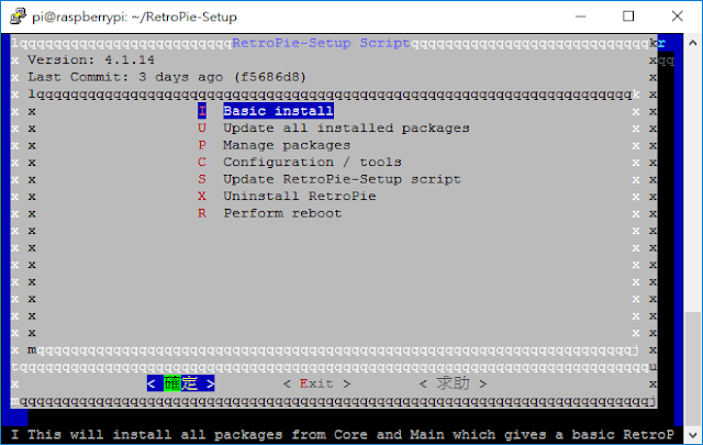
sudo ./retropie_setup.sh


步驟四:開機就進入模擬器
Step 4 : Boot to EmulationStation


步驟五(非必要):安裝 Samba
Step 5(optional): Installing Samba


此刻就可以用Raspberry Pi上的IP位址來分享檔案。
You can share files with your Raspberry Pi's IP address, now.

若想要在Retropie選單上看到PIXEL桌面環境的選項,請參考在Retropie上安裝PIXEL桌面
Refer to Install PIXEL Desktop on Retropie  if you want PIXEL desktop on the Retropie menu.

Led Blinking in Raspberry Pi 3 with Scratch 在樹莓派3用Scratch實作Led燈的閃爍

若您覺得文章寫得不錯,請點選文章上的廣告,來支持小編,謝謝。

If you like this post, please click the ads on the blog or buy me a coffee. Thank you very much.

需要什麼材料:
What you need:
  • LED x 1 (LED x 1)
  • 220 ohm resistor x 1 (200歐姆電阻 x 1)
  • Breadboard 300 holes x 1 (300孔麵包板 x 1)
  • Male-to-female jumper x 2 (公對母杜邦線 x 2)


步驟一:(若是使用 NOOBS v2.1.0版本的話,可略過此步驟)
Step 1: (You can skip this step if you are using NOOBS v2.1.0 or above)

更新Raspbian系統
Updating Raspbian OS
sudo apt-get update
sudo apt-get dist-upgrade

步驟二:從選單-->軟體開發-->Scratch,來開啟 Scratch 1.4 (Linux),之後在Scratch中點選編輯-->Start GPIO server
Step 2: Open Scratch by clicking on Menu --> Programming --> Scratch. Then, click on Edit --> Start GPIO server.

步驟三:接線
Step 3: The circuit.

Led 正極接 RPI3 的 GPIO17 ( Led anode --> RPI3 GPIO17 )
Led 負極接 RPI3 的 GND ( Led cathode --> RPI3 GND)

樹莓派的針腳說明:
Pin Mapping for Raspberry Pi 3:

步驟四:使用廣播積木來設定GPIO17的on與off,訊息分別為 config17outputgpio17ongpio17off
Step 4: Using broadcast block to configure GPIO17 and the messages are config17outputgpio17ongpio17off.


示範影片:
Demo video:

參考資料:
Reference:
[1] https://www.raspberrypi.org/learning/robot-antenna/

Blynk App with NodeMcu

若您覺得文章寫得不錯,請點選文章上的廣告,來支持小編,謝謝。

If you like this post, please click the ads on the blog or buy me a coffee. Thank you very much.

本文說明如何使用Blynk這個App來控制 NodeMcu 的內建LED燈。
This tutorial will teach you how to use Blynk App to control NodeMcu's built-in LED.

需要的器材有:
Needed Material items:
1. 手機 (筆者使用Android手機) Cell Phone (Android Phone was used in this tutorial.)
2. NodeMcu
3. Micro USB Cable

步驟一:
Step 1:

在手機上安裝Blynk App後,需註冊一個帳號,帳戶是使用email當作名稱,密碼自訂,驗証碼(ATUH TOKEN)會寄到這個信箱。
After installing Blynk App on your cell phone, you have to register a new account to receive the ATUH TOKEN.

步驟二:
Step 2:
Arduino IDE 安裝Blynk程式庫
Install Blynk library for Arduino IDE.

由Arduino IDE中開啟檔案 --> 範例 --> Blynk --> Boards_WIFI --> ESP8266_Standalone
In Arduino IDE, open ESP8266_Standalone example which is located at File --> Examples --> Blynk --> Boards_WIFI --> ESP8266_Standalone

檔案需要修改auth、ssid、pass三個地方,修改完成後就可以上傳到 NodeMcu。
According your setting, the auth, ssid, pass are to be modified. Then, you can upload the firmware to NodeMcu.

步驟三:
使用Blynk App設計專案
Use Blynk App to create a new project.

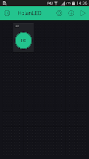
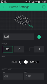
此例只用到一個按鈕作為LED燈的開關,而NodeMcu內建的LED的腳位為D0
For this tutorial, we only need a switch button to control the built-in LED which is on pin D0.

接著在專案中按下Play按鈕,就可以控制 LED 燈。
You can press the play button(the triangle icon) to control NodeMcu's LED.

結果影片:
Demo video:
參考資料:
References:
[1] http://www.blynk.cc/getting-started/

裂项求和(Telescoping Series Sum)

若您覺得文章寫得不錯,請點選文章上的廣告,來支持小編,謝謝。

求下列式子的值:
\[\frac{1}{4\cdot10}+\frac{1}{10\cdot16}+\frac{1}{16\cdot22}+\frac{1}{22\cdot28}+\frac{1}{28\cdot34} . \]

原式可重寫成:
\[\frac {1}{6}(\frac {1}{4}-\frac{1}{10}+\frac{1}{10}-\frac{1}{16}+\frac{1}{16}-\frac{1}{22}+\frac{1}{22}-\frac{1}{28}+\frac{1}{28}-\frac{1}{34})\]

所以答案為 \( \frac {5}{136} \)。


練習題
求下列式子的值:
\[ \frac{3}{1 \cdot 2 \cdot 3} + \frac{5}{2 \cdot 3 \cdot 4} + \frac{7}{3 \cdot 4 \cdot 5} + \cdots + \frac{81}{40 \cdot 41 \cdot 42} = ?\]

答案:\( \frac{ 345} { 287 } \)。

Install PIXEL Desktop on Retropie 在Retropie上安裝PIXEL桌面

若您覺得文章寫得不錯,請點選文章上的廣告,來支持小編,謝謝。

If you like this post, please click the ads on the blog or buy me a coffee. Thank you very much.

Retropie本身的作業系統就是Raspbian,只不過是沒有 PIXEL 桌面的精簡版 (Raspbian lite),於是只要把桌面環境給裝好就有瀏覽器可以上網用了。
Retropie is based on Raspbian OS. However, it is lite version(without Pixel desktop) and user can install Pixel desktop to Retropie from Retropie setup menu.

步驟一:進入 Retropie 選單畫面
Step 1: Enter Retropie menu screen


步驟二:選擇 Retropie 設定( Retropie Setup)
Step 2: Select RETROPIE SETUP

步驟三:選擇 Configuration / tools
Step 3: Select Configuration / tools

步驟四:選擇 raspbiantools - Raspbian related tools
Step 4: Select raspbiantools - Raspbian related tools

步驟五:選擇安裝 Pixel 桌面環境 Install Pixel desktop environment
Step 5: Select Install Pixel desktop environment

步驟六:安裝完成後,可在 Retropie 畫面看到 PORTS 的選項,選擇此選項
Step 6: After installing Pixel desktop, the PORTS option would be accessible from the Retropie menu

步驟七:進入 PORTS 的選單畫面,可看到桌面 (DESKTOP) 選項,選擇此選項即可進入到Pixel 桌面環境。
Step 7: The desktop environment could be accessible from the PORTS menu.

步驟八:恭喜您,進入到 Pixel 桌面環境。
Step 8: Congratulations! You have the Pixel desktop environment.