若您覺得文章寫得不錯,請點選文章上的廣告,來支持小編,謝謝。
If you like this post, please click the ads on the blog or buy me a coffee. Thank you very much.
This tutorial uses a HC-SR04 ultrasonic distance sensor to do an obstacle avoidance car. Before assembling the hardware, the simulation could be done with TinkerCAD circuits.
材料(Materials):
1. Arduino UNO R3 板子 x 1
2. 光感測器模組 HC-SR04 ultrasonic distance sensor x 1
3. 直流馬達 DC motor x 2
4. 杜邦線 jumper wire x 8
5. 麵包板 small breadboard x 1
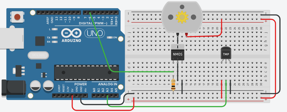
電路(Circuit):

Trig pin is connected to Arduino UNO pin 12.
材料(Materials):
1. Arduino UNO R3 板子 x 1
2. 光感測器模組 HC-SR04 ultrasonic distance sensor x 1
3. 直流馬達 DC motor x 2
4. 杜邦線 jumper wire x 8
5. 麵包板 small breadboard x 1
電路(Circuit):

Trig pin is connected to Arduino UNO pin 12.
Echo pin is connected to Arduino UNO pin 13.
One DC motor is connected to Arduino UNO pin 5 and pin 6.
The other DC motor is connected to Arduino UNO pin 10 and pin 11.
程式碼(The Code):

示範影片(Demo Video):
範例連結(Example Link):
https://www.tinkercad.com/things/8U8fwcfgTbf
One DC motor is connected to Arduino UNO pin 5 and pin 6.
The other DC motor is connected to Arduino UNO pin 10 and pin 11.
程式碼(The Code):

範例連結(Example Link):
https://www.tinkercad.com/things/8U8fwcfgTbf